Synhouse/Synclav.com TX216/TX816 Power Supply Upgrade
Installation Instructions and Photos
The TX216/TX816 power supply upgrade will take a few hours to
install.
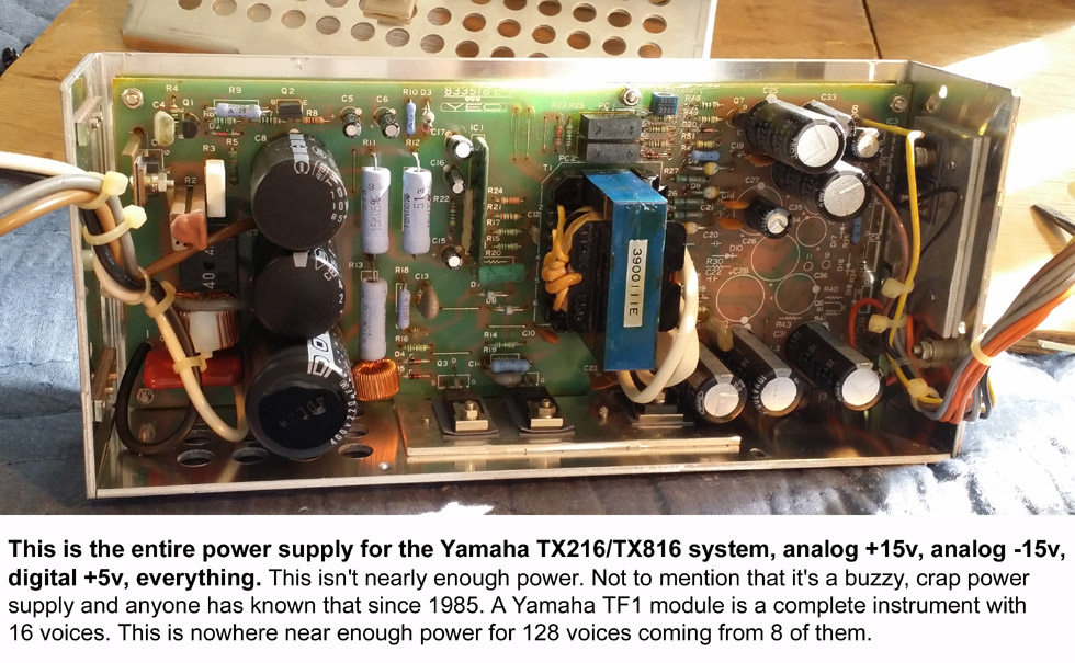
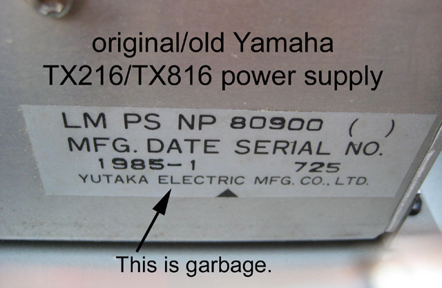
It doesn't matter if your old Yamaha power supply is working
or not or if it is buzzy and humming like crazy or not, as this upgrade
will replace the entire Yamaha power supply, and put an IEC AC inlet in
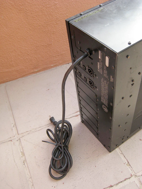
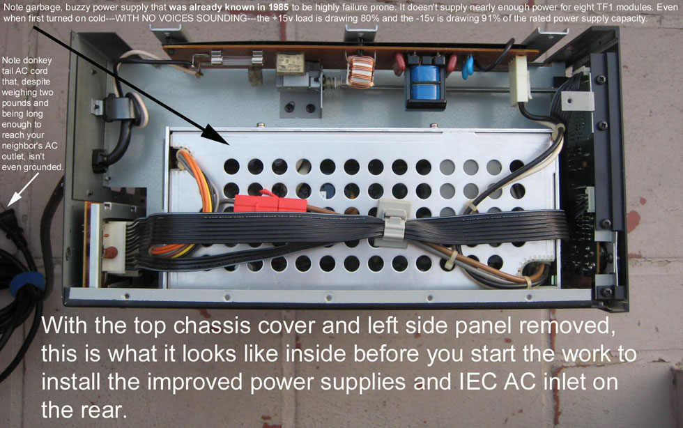
place of the massive ungrounded donkey tail AC cord.
All the way through this project, be careful not to cut your fingers.
The Yamaha TX216 chassis is made of thin, heavy, cheap mild steel with
very, very sharp corners and edges that are sharp because they are not
properly deburred. It can make a nasty cut if you are not careful.
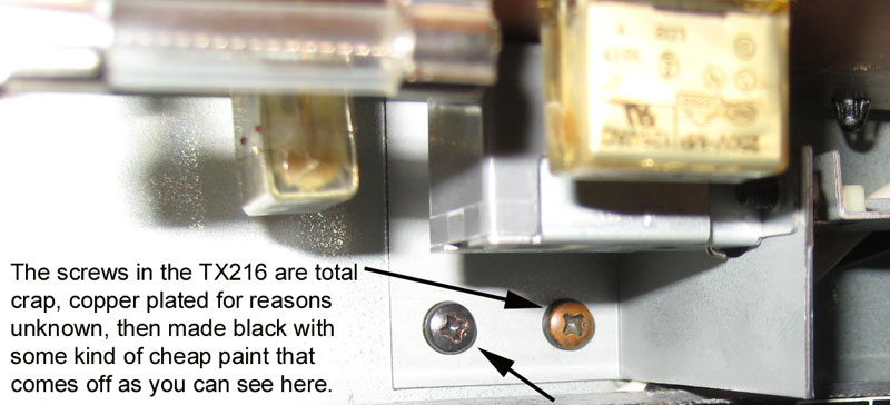
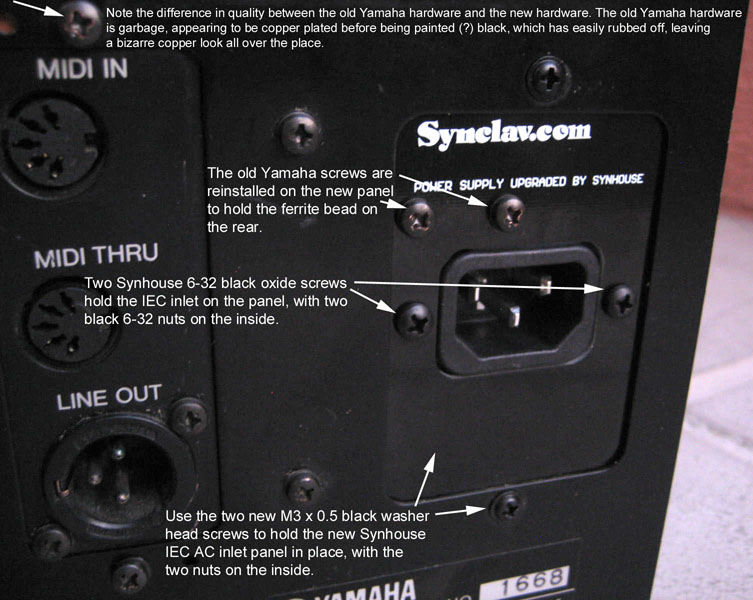
Also take care handling the screws on the TX216, as the hardware is
extremely poor quality. The screws that are supposed to be standard
black screws appear to be copper plated and then covered with some
cheap black paint after that, you'll see that by now that black has
rubbed off on many of them, some of them completely, leaving your
hardware with a bizarre copper look. Copper colored hardware isn't even
a thing, this is just dumb, and crap hardware.
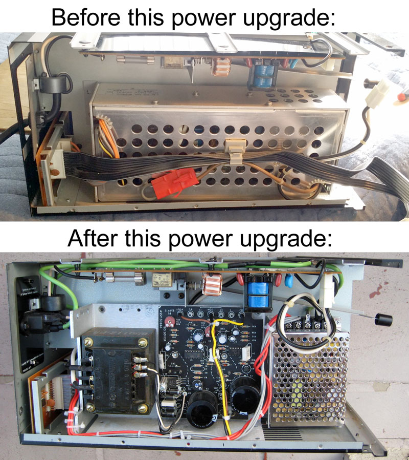
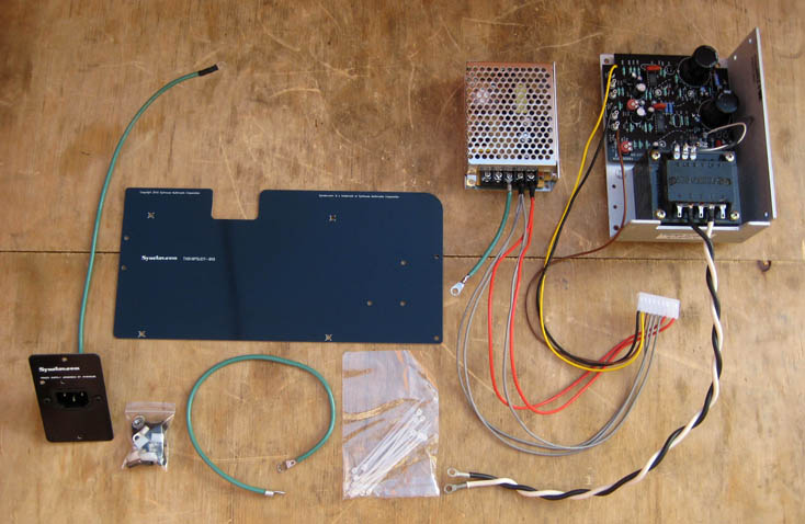
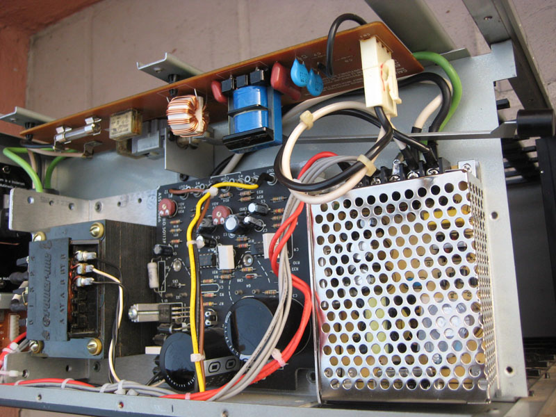
This is the completely pre-assembled power supply upgrade kit you have received:
There are 12 steps to this project.
1) Power down:
Unplug the unit. Even better if it hasn't been powered up for a while, as the capacitors can briefly retain a charge.
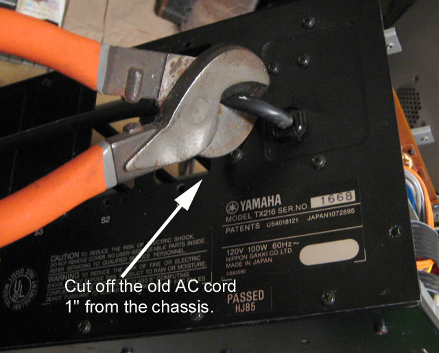
2) Remove old AC cord:
Cut the old ungrounded 2-prong AC power cord off 1" from the back of
the chassis. Having this out of the way will make all the work below a
lot easier as you are spinning the unit around on your workbench. That giant, stupid cord has always been a major annoyance.
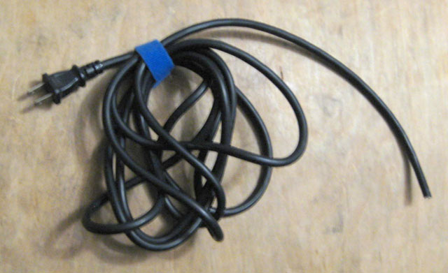
 It's gone now:
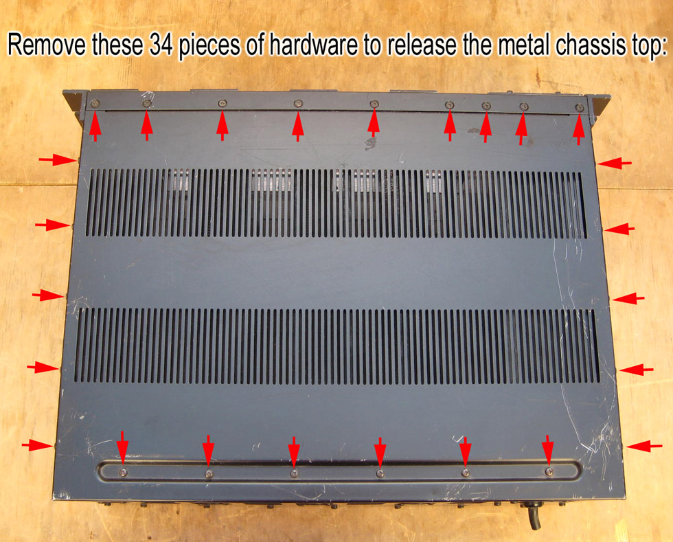
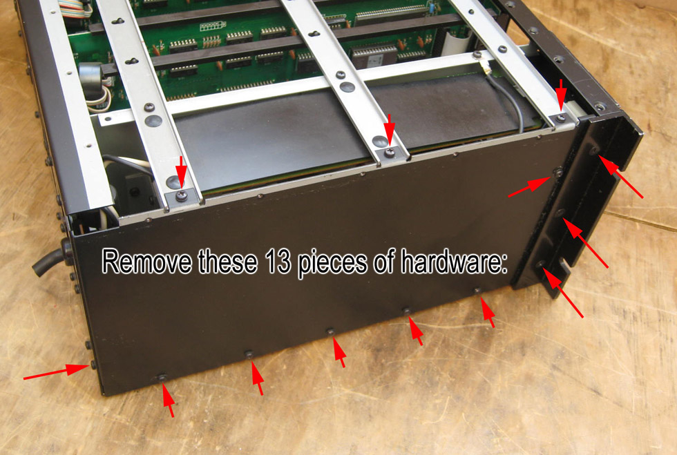
3) Remove metal chassis top and left side panels:
Remove the top chassis panel:
Remove 5 small Phillips screws just over the left edge, remove 5 small Phillips
screws just over the right edge, and remove 6 small Phillips screws from the rear portion of the top side.
Remove 9 countersunk Phillips screws and 9 countersunk tooth
lockwashers from the front portion of the top side, and be SURE to pick each one of
those 9 little countersunk tooth lockwashers out of the indentations,
because they might stick now but they will fall out and get lost later.
Remove the chassis top. You can dust all these pieces off on the
inside once removed. Also note that the mesh fabric meant to keep
debris out of the unit probably shrunk and pulled off in some areas.
You can use contact cement to put it back on.
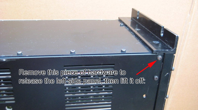
Remove the left (as viewed from the front) side panel to expose the area where all your work will be performed:
Remove 3 small Phillips screws on the top edge.
Remove 5 small Phillips screws from the bottom of the left side.
Remove 1 screw in upper right on left side (near rack ear).
Remove 1 screw in lower right (viewed from rear) side of back panel.
Remove 3 screws to remove left side rack ear. Congratulations to Yamaha, they actually used ten cents worth of aluminum here!
Remove 1 screw on bottom side nearest front/left side.
This was designed with 48 pieces of total garbage hardware holding just
part of a metal box together. The Standard Productions fake TX rack was
a genius metal chassis compared to this pig (but the power supply on
that one was a nightmare from hell, using a computer power supply that
doesn't even have the right voltages for the TF1 modules).
Lift left side panel off. Dust out the inside area.
4) Remove the old power supply and add the new ring terminals:
Locate the white and black AC wires coming out of the power supply, and
cut them off 1" from the hole they come out of, leaving 1" still
sticking out in case someone desperate needs to reuse the power supply to fix a
dead TX216/TX816.
If you've seen upwards to 25 of these old Yutaka Electric power
supplies for sale for very attractive prices on eBay 2019-2020, it's
because people have installed Synhouse and are moving on...
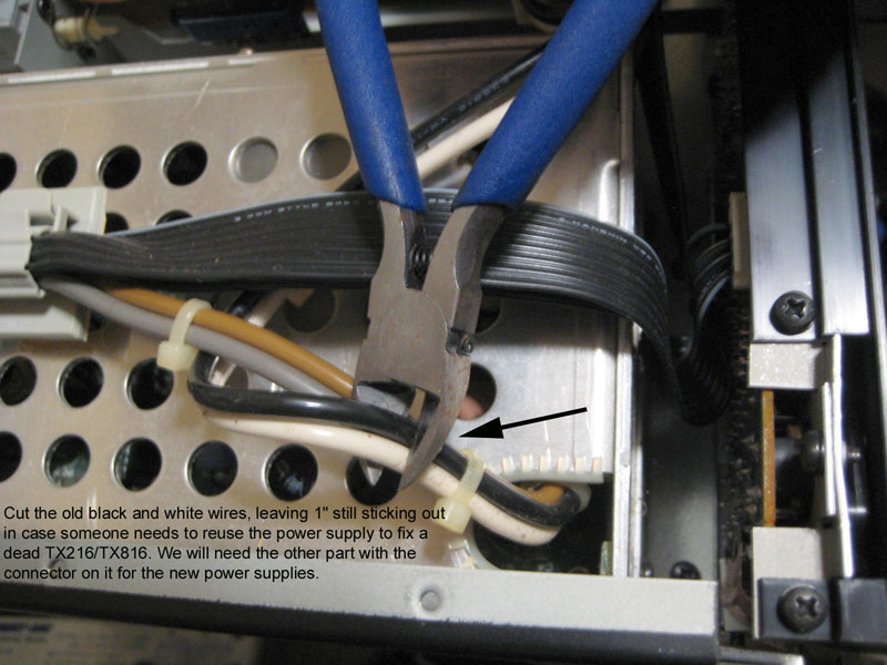
We will need the other half of this wiring (the part with the connector
on it) to connect the new power supplies, so go ahead and temporarily
unplug the other end of this connector to give yourself some space to
work, and add the supplied new ring terminals to the internal AC
connector wiring harness. Strip the ends of the black and white AC
wires that you just cut (this one is about 7" long and has the white
Yamaha connector on the other end), push the supplied 2 short pieces of
heat shrink tubing onto those wires, far enough back so they won't melt
yet, and solder the supplied new ring terminals on them.
This is the Synhouse way throughout, solder everything, crimp nothing;
The connection will never go cold and it lasts forever.
Slip the heat shrink tubing over the shanks of the newly soldered ring
terminals, and shrink the tubing with a heat gun if you have it, or by
holding your soldering iron very close to it so that it melts and
shrinks. Don't touch it, or else it will burn a hole.
Remove the gray plastic clip that is stuck (or used to be stuck, the
crap adhesive they used didn't last) to the side of the old power
supply, and free up the wires.
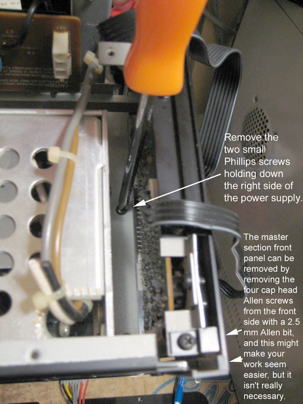
Unplug the 12-way black flat cable at the rear to get access to the
power supply area. This goes to the PCB on the back of the master
section front panel. This panel can be removed by removing the four cap
head Allen screws from the front side with a 2.5 mm Allen wrench (or
better yet, a 2.5 mm Allen bit in a driver handle if you have it), and
this might make your work seem easier, but it isn't really necessary.
It was removed for the test installations just to be able to let some
light in there to take clearer photos.
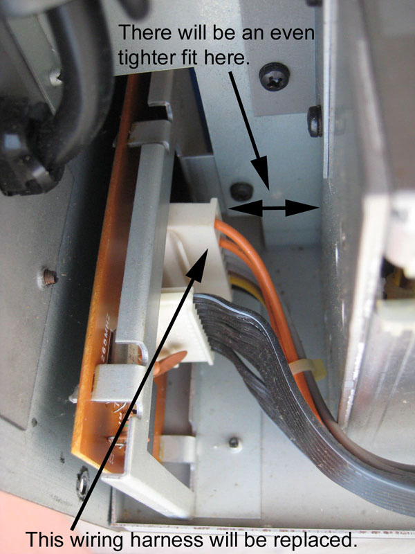
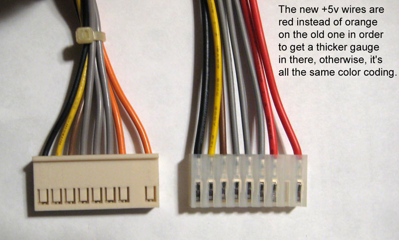
Unplug the 8-way multicolor cable at the rear. This is where the new, improved power supply wiring harness will connect.
The new +5v wires are red instead of orange on the old one in order to
get a thicker gauge in there, otherwise, it's all the same color coding.
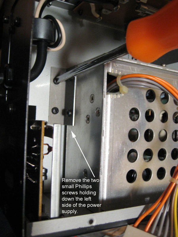
Remove the 2 small Phillips screws holding down the left side of the power supply.
Remove the 2 small Phillips screws holding down the right side of the power supply.
Keep those 4 screws for now, we will need them once again to hold the Synhouse drilling template in place.
Remove the old power supply. Again, be careful, the corners of the
mounting brackets are as sharp as needles. You can dust it out a little
more now.
5) Drill the 7 new mounting holes for the two new power supplies:
Remove any TF1 modules in slots 1-4. That should give your hands
enough workspace, depending on the length of the screwdrivers you are
using.
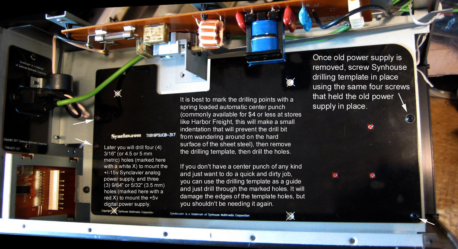
Screw the Synhouse drilling template in place using the same 4 screws that held the old power supply in place.
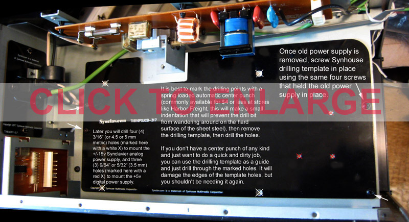
It is best to mark the drilling points using the drilling template,
remove the template, then drill the holes. Each of the holes that need
to be drilled are marked on the drilling template with a white X.
It's easiest to first mark the drilling points with a spring loaded
automatic center punch (commonly available for $4 or less at stores
like Harbor Freight),
this will make a small indentation that will prevent the drill bit from
wandering around on the hard surface of the sheet steel. You can also
use a regular center punch and hit it with a hammer, but go gently,
that steel is very thin and can be dented without too much force. About
1 second after you pull the trigger on your drill, you'll wish you
marked those holes first...
Mark the drilling points and remove the drilling template.
If you don't have a center punch of any kind and just want to do a
quick and dirty job, you can use the drilling template as a guide and
just drill through the marked holes. It will scoot around and damage
the edges of the template holes, but you shouldn't be needing it again.
The holes won't be in the precise locations in this case, but probably
close enough.
It would be a good idea to set the TX216 on its right side with the
(removed panel) left side up, and put an old shirt or something inside
(on the back of the module in slot 5 if there is one there) to catch
the metal bits when they start falling down as you drill the holes.
This will make cleanup easier.
Now that it is time to drill the holes, this is where those little
indentations from the automatic center punch start to pay off, because
now you can see that the four largest holes are very close to the sides
of the metal and the transformer on top, so your drill will have to be
tilted by at least 20 degrees as you drill (unless you have some very,
very long drill bits, which would be wonderful, but sizes this small
are usually very short), and those indentations really help you keep
drilling down into the metal instead of sliding off the mark again and
again.
You COULD take this metal panel out of the TX216 for drilling, but
that's a lot of work, it wasn't done that way here, and it's a flimsy
steel panel that will bend when you have it out and try drilling it,
and then you'd need to have some scrap wood or something to put under
it as you drill through. Just leave it securely mounted in place and
drill right there, it's better that way.
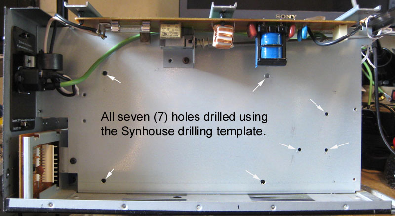
Drill four (4) 3/16" (or 5 mm metric) holes to mount the +/-15v Synclavier analog power supply.
Drill three (3) 9/64" or 5/32" (3.5 mm) holes to mount the +5v digital power supply.
You can use a much larger drill bit (3/8" or so) twisted in your
fingers to clean up drilled holes, to deburr the edges on both sides of
the hole. This isn't necessary, it's just a part of doing good, clean
work.
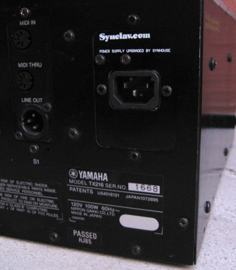
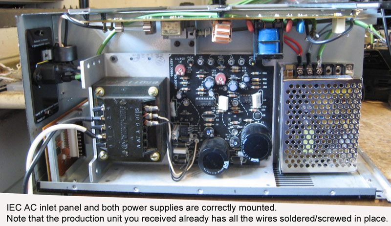
The new TX816IEC panel/AC inlet assembly probably arrived fully
assembled (2 Synhouse 6-32 black oxide screws hold the IEC inlet on the
panel, with 2 black 6-32 nuts on the inside).
Using a razor or hobby knife, carefully cut through the black
insulation jacket on what remains of the old AC cord, both inside the
panel and out, without cutting the white and black wires inside, and
pull the pieces of that the black insulation jacket out and throw it
away.
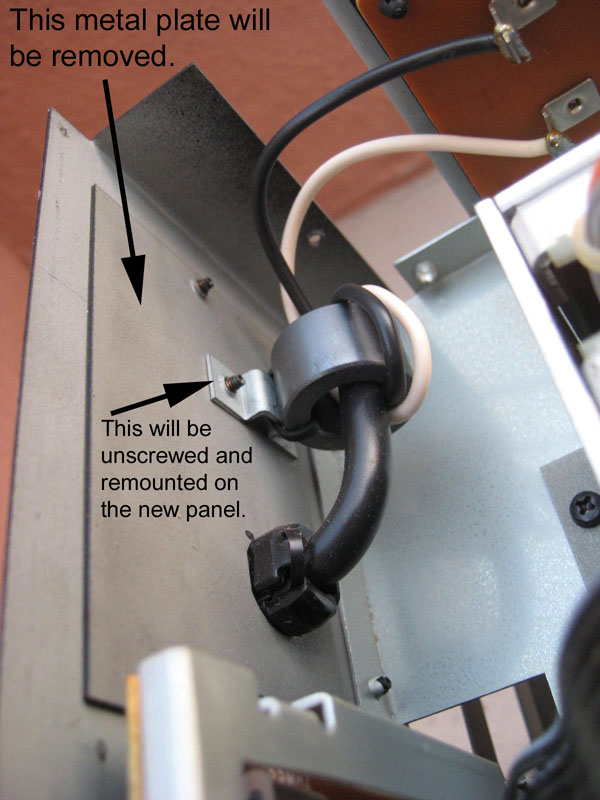
Unscrew the 2 screws holding the ferrite bead in place. Keep the screws, we will need to reuse them.
Unscrew the 2 screws holding the old metal panel surrounding the old
cut off AC cord and pull the panel out. You won't need this anymore.
Strip the ends of the black and white AC wires that you just cut
from
the old AC power cord. Push the supplied 2 short pieces of heat shrink
tubing onto those wires, far enough back so they won't melt yet, and
solder those wires onto the two unused terminals of the new AC IEC
inlet. Looking at the back side of the new AC IEC inlet with the
ground/green wire being on the bottom, the terminal on the left is L or
line for the black wire, and the terminal on the left is N or neutral
for the white wire. You can see the L and N marked/molded into the
plastic right next to the terminals, but the letters are written upside
down. Slip the heat shrink tubing over those newly
soldered joints and shrink the tubing with a heat gun if you have it,
or by holding your soldering iron very close to it so that it melts and
shrinks. Don't touch it, or else it will burn a hole.
Use the same 2 old screws to reattach the ferrite bead to the new TX816IEC panel/AC inlet assembly.
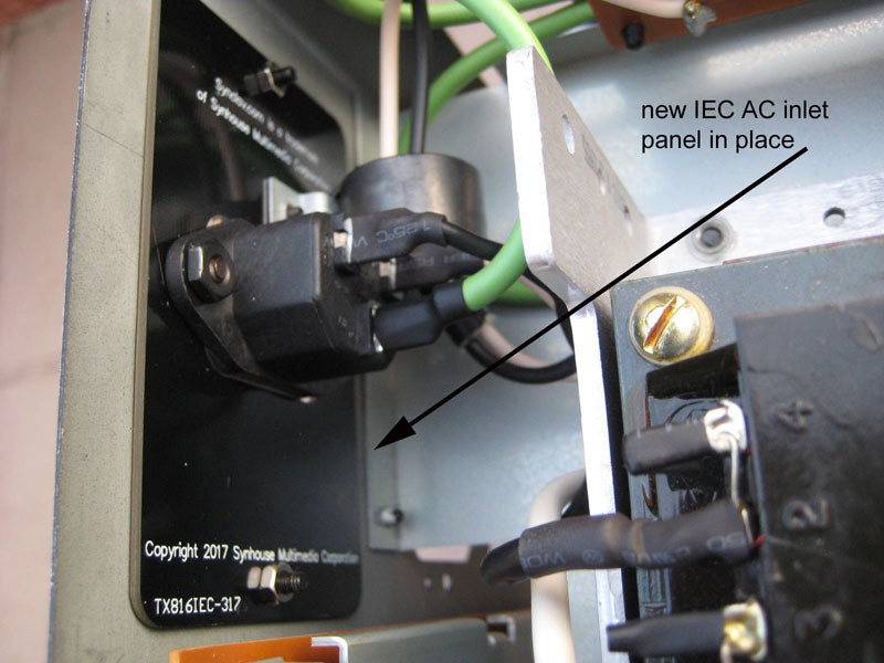
Install the new TX816IEC panel/AC inlet assembly (with 33 cm green
ground wire already soldered onto it) in place of the old metal AC cord
panel, using the supplied 2 new M3 x 0.5 black washer head screws, with the two M3 spring washers and two M3 x 0.5 nuts on the inside. You can leave the 33 cm green ground wire disconnected for now.
7) Mount the new power supplies and add green safety ground wire:
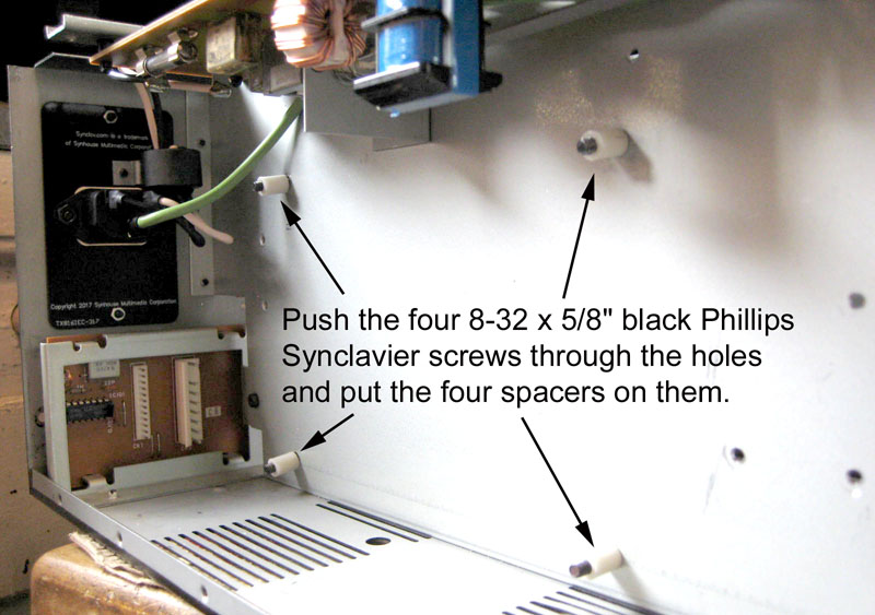
Push the four 8-32 x 5/8" black Phillips Synclavier screws through the
holes from the card cage side and put the four spacers on them from the
power supply compartment side. Try not to knock these off as you fit
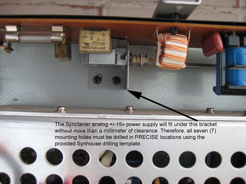
the +/-15v analog power supply into place. It is a very tight fit that
requires some twisting going in, and it ends up without even a
millimeter of clearance to spare above it.
Be very careful handling the +/-15v analog power supply, do not touch,
push, or put any pressure on the two large electrolytic capacitors on
it, their solder joints can break easily. Handle it by the aluminum
chassis only.
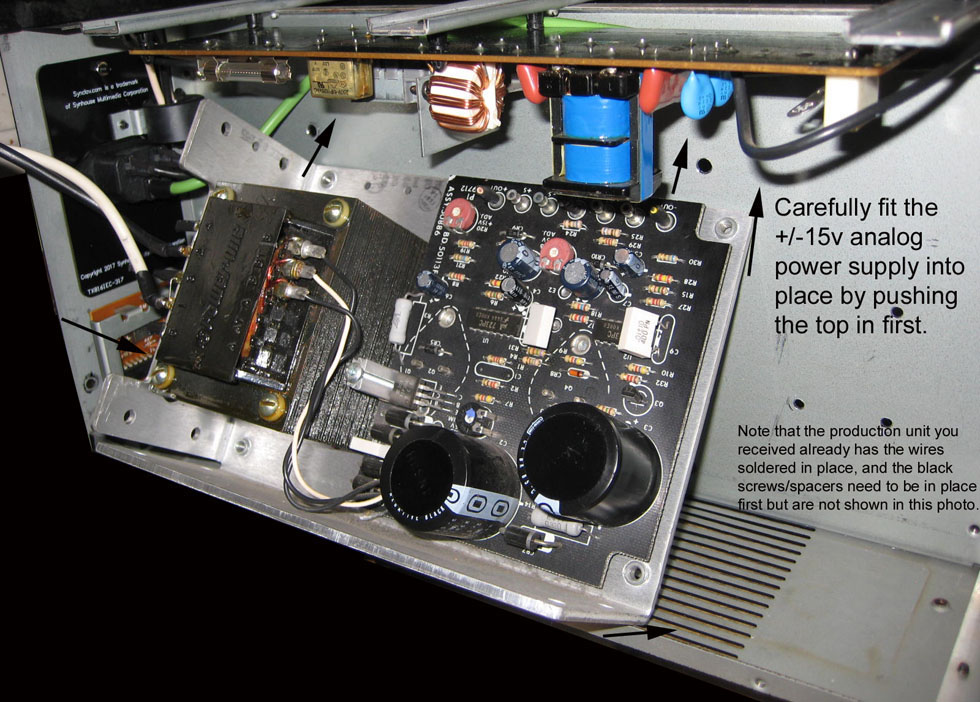
Carefully fit the +/-15v analog power supply into place by pushing the
top in first to get that part under the Yamaha AC switch bracket, then
push the lower part in over the Yamaha lower chassis flange.
Once the +/-15v analog power supply is in place, place the ring
terminal end of the 13"/33 cm green ground wire behind the upper left
corner of the +/-15v analog power supply and make sure the mounting
screw/spacer holds it there, and screw all 4 screws in tightly.
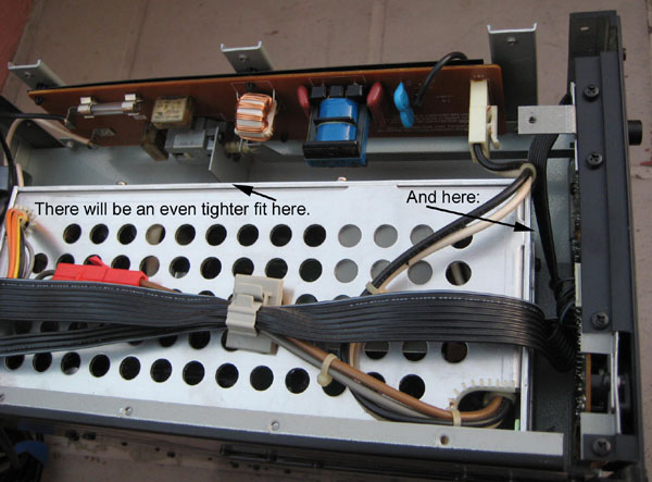
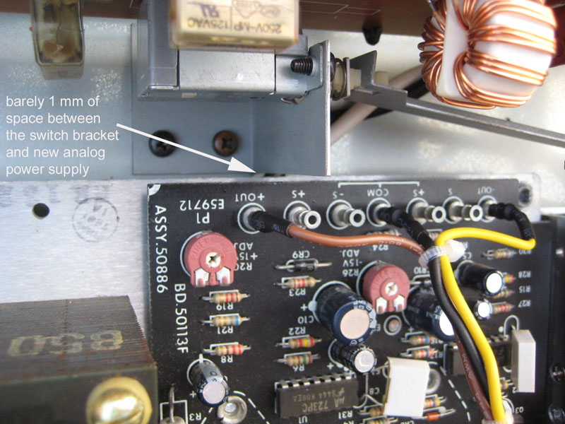
If you did this correctly, drilling and all, there will be less than 1
mm of space between the top of the power supply and that Yamaha AC
switch bracket. If there were more than 1 mm of space there, then it
wouldn't fit, as the bottom side is already on the floor of theYamaha chassis.
Screw the +5v digital power supply tightly in place using the supplied 3 new M3 x 0.5 x 5 mm black screws.
8) Connect the AC power wiring to the +5v digital power supply:
You previously added ring terminals to the Yamaha black and white wires
with the white connector on the other end, now carefully remove the
line (AC-L) and neutral (AC-N) screws from the terminal block of the
+5v digital power supply. They already have the black and white wires
that go to the transformer on the +/-15v analog power supply on there,
but you need to add these black and white wires with the white
connector on the other end to those points.
Once that is done, confirm that the black and white wires are going
from the new IEC AC inlet to the Yamaha AC board, then out the white
connector on that board to the AC-L and AC-N connections on the +5v
digital power supply, then from there on to the transformer on the
+/-15v analog power supply. This powers everything.
At
this time it actually isn't known what the Yamaha AC board is doing or
why it has an inductor coil, a relay, a large transformer, and a bunch
of capacitors. All it provides for our purposes is a fuse for the AC
line and the AC power switch, and nothing else on it would be needed
for this. But we still leave it inline there, as the TX216 has the
convoluted design of having a PCB-mounted AC switch when the switch is
actually needed 10" away, and there is a 10" sheet metal rod with very
sharp edges actuating this switch remotely.
The issue here for European users is that
this board might blow up with 230v connected to it (if it is the USA
model TX216 as shown in these photos that is marked 120v only), or it
might be okay. It's up to the user to make this determination if
needed, and best to do that by checking the TX216 service manual.
Both of these Synhouse supplied power supplies can work on 115v for USA, or 230v for Europe (or 100v for Japan, etc.).
The Synclavier +/-15v analog power supply is a world power unit, and
the transformer pins can be jumped as per the markings on the front of
it for any power in the world.
The +5v digital power supply is an autosensing world power unit, so no
changes are needed there, and it also has an AC line fuse inside it.
Worst case, the traces on that absolute shit garbage single sided paper phenolic PCB Yamaha AC board can
be cut, some jumper wires soldered, so that all the board is doing is
taking the power in from the AC inlet, running it across the AC fuse,
then going through the AC switch, then out the white connector.
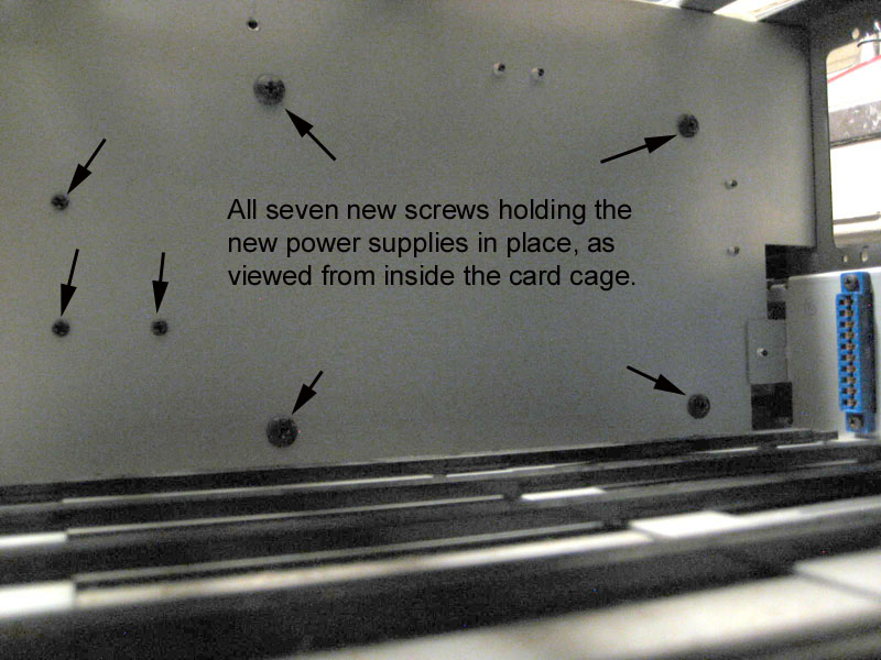
9) Connect the safety frame grounds:
The Yamaha AC power board on top always had a short black wire ground
strap connected by a screw to the top edge flange of the steel panel
that you just drilled 7 holes in.
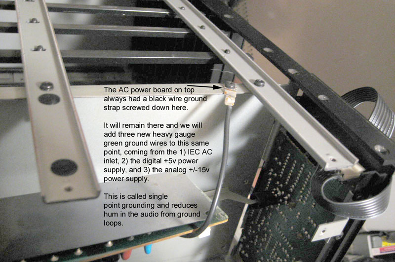
Note the connection, and remove that
screw so we can add 3 more ground straps to be held by that same single
screw.
That black Yamaha ground strap will remain there and you must add the three new heavy gauge green ground wires to this same
point, coming from the 1) IEC AC inlet, 2) the digital +5v power supply, and 3) the analog +/-15v power supply.
This is called single point grounding and reduces hum in the audio from ground loops.
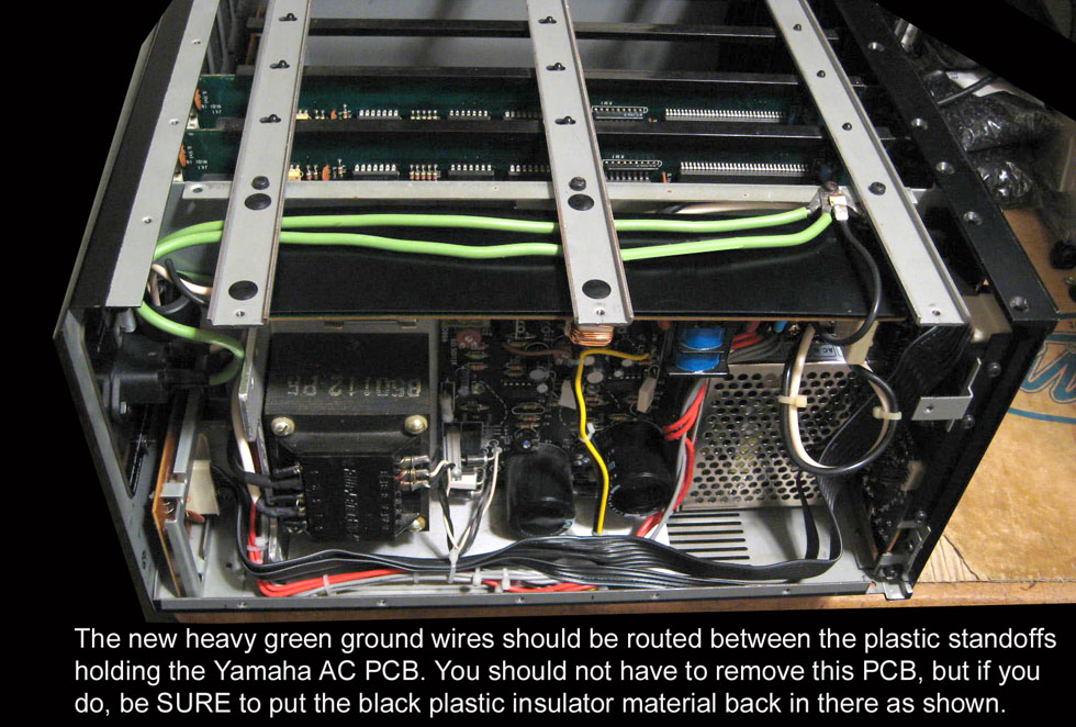
You should route those two longest (13" or 33 cm) green ground wires
carefully between the plastic spacers holding the Yamaha AC board in
place. The wires should be on the top side as shown in the photos, with
the plastic insulator sheet under it. If you try to do it any other
way, it will be pressing down on the edge of the flimsy Yamaha AC board
and might crack it or break a trace. Running them over the top between
the spacers will put no pressure on it.
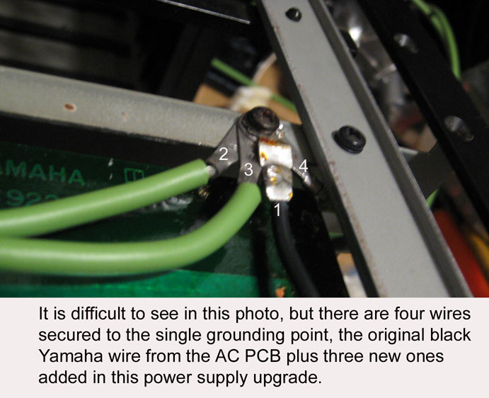
Note that the very flat star
washer/ring terminal ends of the green ground wires are the ones that
go on this single grounding point, as they are flat and very thin and you will
be stacking four of them to be held by that one screw.
Put that screw back in place and make
sure it is tight, and that it has four wires on it (1 black, 3 green)
as shown in the photo.
10) Partially reassemble and clean up your work:
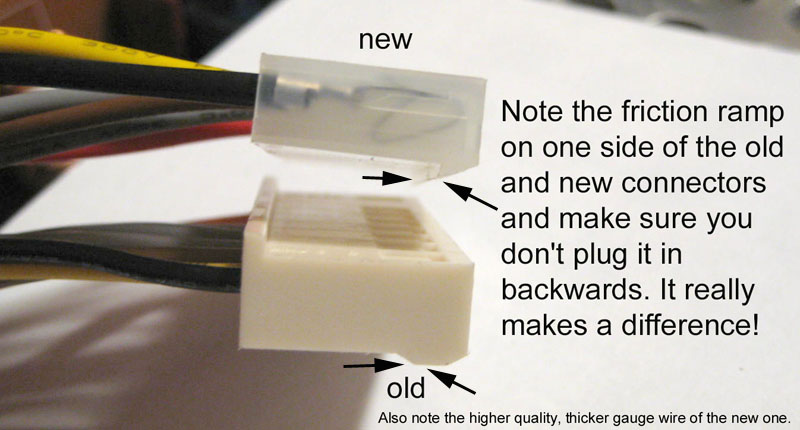
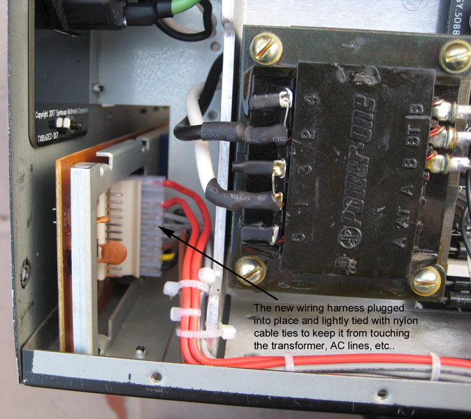
Plug the new 8-way
red/gray/brown/yellow/black power supply wiring harness into the board
at the rear. Note the friction ramp on one side of the old and new
connectors (shown in the photo here) and make sure you don't plug it in
backwards. It really makes a difference!
Plug the 12-way black flat cable into the board at the rear.
If you removed the master section front panel, then put it back on now.
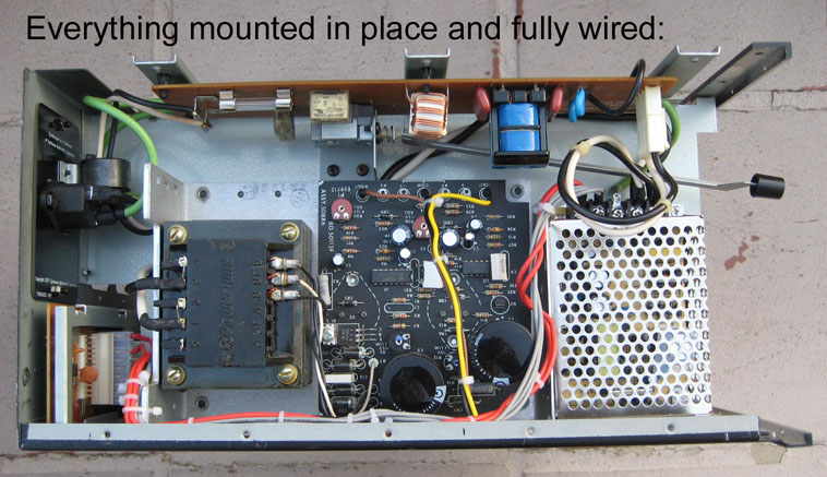
Use the supplied nylon cable ties to tie up the wires as shown in the photos.
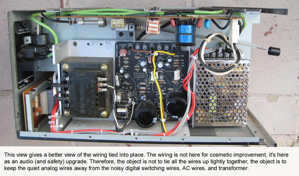
This
improved wiring is not here for cosmetic improvement, it's here as an
audio (and safety) upgrade. Therefore, the object is not to tie all the
wires up tightly together, the object is to keep the quiet analog wires
away from the noisy digital switching power supply, AC wires, and
transformer. So you can see in the photo below that the temptation to
tie the brown/black/yellow analog power wires together with all the
red/gray wires along the side of the +5v power supply was resisted,
those wires were run straight down to keep them away from the circuitry
of the +5v power supply.
The cable ties are only meant to
hold the quiet analog wires away from the noisy AC components and to
keep them from getting pinched when the chassis side panel is
reinstalled.
Be sure that all the wires
coming from the top side of the digital +5v power supply (and
everything else, such as green ground wires) are not rubbing and
inhibiting the movement of the sharp-edged long sheet metal rod that
actuates the AC switch. If they were, the sharp edges could potentially
cut through some of the insulation on the wires over time (but you can
see that the Synhouse AC wires are the highest quality possibly, very
thick insulation with pure copper conductors, the DC wires are the
thickest gauge available that would fit the connector receptacle
housing).
Don't put the TF1 modules from slots
1-4 back in just yet, and in fact having ALL of the TF1 modules removed
would be okay for the first power-on test.
11) Test and adjust as needed:
Make sure that none of your tools,
drill bits, spare wires, etc. are sitting on top of the Yamaha AC board
or anywhere else in there, then plug in an IEC AC cord (a regular
computer cord), and turn the power on.
You should see the green power
indicator LED running inside the digital +5v power supply, and the LEDs
on the master section front panel will light up, and the LEDs on any
TF1 modules that are installed.
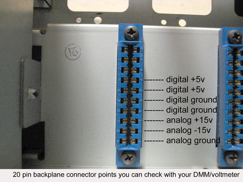
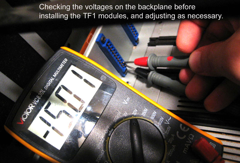
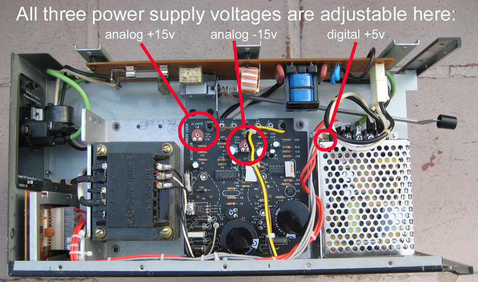
Although the voltages should have
been properly adjusted before shipment, you can confirm and use your
DMM/voltmeter to check the voltages following the pinout shown in the
photo.
Each power supply voltage is individually adjustable with a screwdriver at the three points shown in the photo.
These are both very strong power supplies that are significantly
overrated for this application, so even if adjusted to exactly +5.0v,
+15.0v, and -15.0v with no TF modules powered, it's not likely to have
much voltage droop when they are in there later.
12) Reassemble the chassis:
If everything looks good and is working properly, reinstall the left side panel.
Reinstall the chassis top.
Reinstall any TF1 modules that were removed.
The 2 screws holding the old metal AC
cord panel and the 4 screws holding the old power supply in place are
the only screws that are not needed anymore, so if you have more than 4
screws left over, check your work and make sure all the old screws that
are still needed have been reinstalled correctly.
The weight of a TX216 with two TF1
modules is 21.5 pounds, after this upgrade it will weigh 23.3 pounds,
so this upgrade adds approximately 1.8 pounds.
Your Yamaha TX216 is now ready for
use with greater electrical safety, a lower noise floor, improved
transient response, better dynamic range, and for the first time ever
it has 1) enough power for 8 TF1 modules and 2) a tremendous amount of
power headroom.
Copyright © 6/25/2019 Synhouse Multimedia Corporation
last updated 10/27/2020